EIGHT CYLINDER HYDRAULIC SYSTEM CONTROL
Some machines are driven by a hydraulic system made up of a pump, a main valve plus secondary valves whose job is to move the machine's cylinders. In this problem we are going to control an eight cylinder machine. We will focus on just the secondary valves which will be of the double effect type.
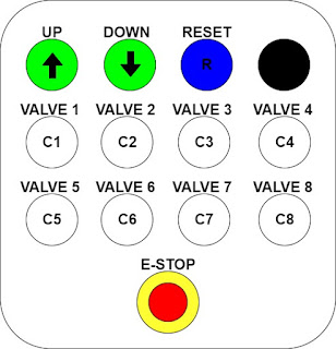
The operator will control the up and down movements of the cylinders with a cable pendant,
The UP and DOWN push buttons are pulse signals while C1 through C8 are level signals. In order to operate the machine he must first choose the upwards or downwards direction by pressing and inmediately releasing the UP or DOWN push buttons. Then he must proceed by selecting the cylinder he needs to work with by pressing one of the eight buttons C1 to C8. As long as he keeps the button pressed down the cylinder will move but it will come to a stop as soon as it is released. For safety reasons there is also an E-Stop and a RESET push buttons.
As per EN 60204-1 Safety of Machinery, the push buttons to handle the cylinder movements must be white, the RESET blue and the E-Stop mushroom shall be red on a yellow background. We will use green light push buttons for the UP and DOWN selection.
First of all we are going to study the control of just one cylinder. Then it will become easy enough to expand the program to control the whole set of the eight cylinders.
The first thing we need to come up with is the state diagram for a one-cylinder machine.
There are three states. The machine is at rest at state S0 = (q1,q0) = (0,0). If we push the -U button we go to state S1 = (0,1) and we can start the cylinder movement by pushing the -VA (valve) push button. Pressing on -U again it will take us back to the rest state S0. If we press on -D we change the machine to state S2=(10) and again we can start the motion of the cylinder in the opposite direction.
The state diagram is fairly simple and getting the input and ouput equations is straightforward. Since we are going to be using the master-rank SR flip fllops, the excitation equations will become,
S0 = q1'·q0'·U
R0 = q1'·q0·U
S1 = q1'·q0'·U
R1 = q1·q0'·D
and the output equations,
Z0 = q1'·q0·VA
Z1 = q1·q0'·VA
We notice that the output equations are functions of both the present states and the input so what we have is a Mealy model machine.
We can simulate the state diagram by implementing the equations in the CADeSIMU simulation software,
From the simulation it becomes clear that in order to increase the number cylinders all it has to be done is to add more digital inputs and the corresponding AND operators. However the number of states will remain the same. The LOGO!8 program in a FUP diagram for the eight cylinders,


