WATER LEVEL CONTROL PROCESS
Original post on the Facebook group Industrial Automation Using PLC and SCADA by Romel Roy.
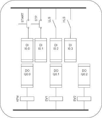
The inputs are 4 NO switches: push button START, pushbutton STP for the stop function, high and low level sensors, that is HLS and LLS. The outputs are 3 NO switches: pump motor (KPM), water inlet electrovalve EV1, and water outlet/drain electrovalve EV2. So we actually have I/O = 4/3. Initial condition: the tank is empty.
Initially, the START pushbutton is pressed on, the motor starts and EV1 opens. The water level in the tank raises up until HLS is activated. Accordingly the motor turns off and EV1 closes. Next, EV2 opens and the water level is lowered. Eventually LLS will become deenergized at which point the process is reinitiated. When pressing on the STOP pushbutton the process will stop.
We first draw the GRAFCET diagram for the process stated above,
At state 1 both KPM and EV1 are on and the water tank is filling up. The transition to state 2 is going to happen when the water reaches the maximum allowed level and consequently the high level sensor is energized. Thus HLS, from a logical standpoint, is an asserted high signal and we depict it on the GRAFCET diagram as simply HLS.
The last one is state 2. EV2 is energized and the tank is being emptied. This will go on until getting a low level signal from the LLS sensor. At this point the process reinitiates by returning to state 1 and repeats itsel until the an operator presses on the STOP pushbutton.
The PLC input/output configuration,
The next step will consist in writing the PLC ladder program,
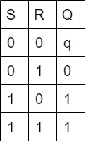
Since we are going to be programming the S7-200 CPU 214, the logical truth table for the SR flipflop is given by the Siemens S7-200 system manual,
where "Q" is the next state and "q" is the present state. Since the inputs S and R to the latch and its output are asserted high signals, the logical "0" is equivalent to a low voltage level at the DI and the logical "1" means there is a high level voltage coming from the DI. It is worthy to notice that if both inputs are a logical "0" the next state is going to remain equal to the present state, that is to say it has a 1-bit size memory.
The actual S7-200 PLC program is done with STEP 7 MicroWin. We have defined the variables on the symbol table,


